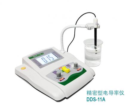
an overview of the
dds-11a digital display conductivity meter is a precision instrument used to measure the conductivity of various liquid media in laboratory. when equipped with 0.1, 10 constant conductance electrodes, high pure water conductivity or high conductivity water can be accurately measured.
main design features of the instrument:
& bull; high reliability and stability
& bull; advanced circuit structure
& bull; output measuring signal
& bull; high definition digital display (word height 20mm 3 1/2 bit)
technical performance
1. equipment operating conditions
power supply: ac220v± 10%v, 50 hz /60hz
to ensure accurate and reliable instrument measurements, please use the following environmental conditions: environment
temperature 0 ℃ ~ 40 ℃; air relative humidity ≤ 85%; no significant vibration, strong magnetic interference
2. main technical parameters
measuring range 0 ~ 2× 10⁵ (& mu; s/cm)
accuracy & plusmn; 1% f * s
instrument stability: 0.5%
temperature compensation scope 15 ~ 35 ℃)
output measuring signal 0 ~ 20(mv)
instrument appearance size 240× 170 & times; 60 (mm)
instrument weight: 0.7 (kg)
power consumption: 3 (w)
specification constants: 0.01, 0.1, 1, 10
electrode specification constant
0.01
0.1
1
(light)
1
(platinum black)
10
applicable range of measurement μ s/cm
0 ~ 3
0.1 ~ 30
1-100
100 ~ 3000
more than 1000
this instrument is equipped with one (standard set) conductive electrode (platinum black), whose specification constant j0=1. other specification constant electrode, the user according to need another match.
2. scope of instrument range display
this instrument has four ranges
when the specification constant j0=1 electrode is selected for measurement, its range is shown in table 2.
when j0=1 in table 2, the corresponding range of each range segment of the instrument is displayed
the serial number
range switch position
instrument display range
corresponding range display range (μ s/cm)
1
20 & mu; s.
0 ~ 19.99
0 ~ 19.99
2
200 & mu; s.
0 ~ 199.9
0 ~ 199.9
3
2 ms
0 ~ 1.999
0 ~ 1999
4
20 ms
0 ~ 19.99
0 ~ 19990
note: range 1 and 2, unit μ s; range 3, 4, ms. its relation: 1μ s = 10-3 ms = 10-6 s
when choosing constant electrodes of other specifications, the range of their range is shown in table 3.
table 3 shows the range of the constant electrodes of other specifications
sequence
no.
range
switch setting
instrument display range
select electrode specifications and constants
corresponding range display range (μ s/cm)
j0 = 0.01
j0 = 0.1
j0 = 10
1
20 & mu; s.
0 ~ 19.99
(0 ~ 19.99) & times; 0.01
(0 ~ 19.99) & times; 0.1
(0 ~ 19.99) & times; 10
2
200 & mu; s.
0 ~ 199.9
(0 ~ 199.9) & times; 0.01
(0 ~ 199.9) & times; 0.1
(0 ~ 199.9) & times; 10
3
2 ms
0 ~ 1.999
(0 ~ 1999) & times; 0.01
(0 ~ 1999) & times; 0.1
(0 ~ 1999) & times; 10
4
20 ms
0 ~ 19.99
(0 ~ 19990) & times; 0.01
(0 ~ 19990) & times; 0.1
(0 ~ 19990) & times; 10
k = d× j
k: measured liquid conductivity; d: instrument display value; j: specification constant of conductance electrode.
3. operation
first case: no temperature compensation (basic law)
1 & ndash; 1. constant correction
for electrodes of the same specification of constant, the range of the actual conductivity cell constant is j1= (0.8 ~ 1.2) j0. in order to eliminate the actual deviation, the instrument is provided with constant correction function.
operation: turn on the power switch, timely isothermal. temperature compensation button buy 25 ℃ scale value. set instrument measuring switch ‘ the correction & rsquo; & rsquo; adjust the constant correction button to display the actual constant (coefficient) value of the battery. when j1=j0, the instrument displays 1.000; when j1=0.95j0, the instrument shows 0.950; when j1=1.05j 0, the instrument displays 1.050. as shown in table 4.
specifications
constant
j0
j1 = 0.950 j0
j1 = 1.050 j 0
j1
constant correction display
j1
constant correction display
0.01
0.0095
0.950
0.0105
1.050
0.1
0.095
0.105
1
0.95
1.05
10
9.50
10.5
whether the electrode is connected, and where the instrument range switch is, does not affect the constant correction.
when the new electrode is delivered from the factory, its j1 is generally marked at the corresponding position of the electrode.
